

Nec Electronics Usb 3.0 Host Controller
Introduction: USB Wii Archetype Controller
This project will show you lot how to create a real USB game pad using a Wii Classic Controller.
Through the steps, you will learn almost:
- How USB works
- How I2C works
- How to read information from the Wii Classic Controller
Some of these pre-requisite skills would be overnice
- General electronics
- AVR programming
The code volition be based on 5-USB, and the circuit will exist based on a implementation Five-USB instance circuitry chosen USnooBie.
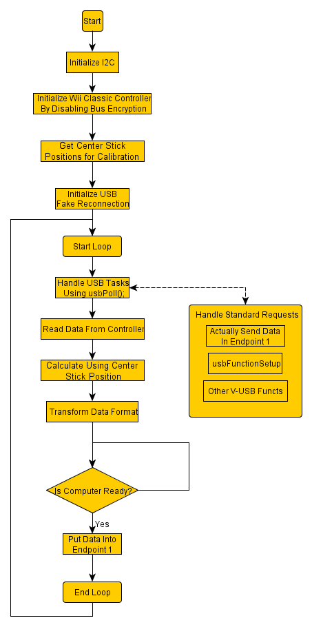
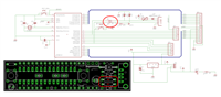
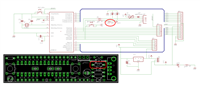
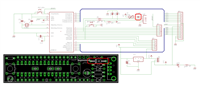
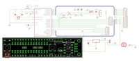
The entire project is provided every bit a ZIP file download below. Too see below for a flowchart of how the code will work.
Step 1: Using the AVR With V-USB
For the microcontroller, we'll be using a ATmega328P. This microcontroller has enough memory resources and a built-in TWI/I2C peripheral to accomplish our goals. However, it does non have built-in USB, which is a problem that we are going to solve using 5-USB.
"Five-USB is a software-only implementation of a depression-speed USB device for Atmel'southward AVR® microcontrollers, making it possible to build USB hardware with nearly any AVR® microcontroller, non requiring whatever boosted chip."- V-USB official website
V-USB uses a set of hardware and some very special assembly programming techniques to scrap-bang the non-render-to-nada (NRZ) binary code that USB uses to communicate. The files provided by Five-USB will be compiled into our program in lodge to create a USB device with our ATmega328P
Please visit the download section of V-USB'south website to obtain a re-create of the latest version. In my projection source code, information technology's already included.
To compile Five-USB into your project...
- Make certain you've defined the processor and clock speed correctly (V-USB only supports certain clock speeds)
- Re-create the binder "usbdrv" from the downloaded parcel into your project folder
- In your project manager or makefile, include "usbdrv.c" and "usbdrvasm.S", such that the object file that's generated will become linked into your project
- Within the folder "usbdrv", there is a "usbconfig-prototype.h", copy that file into your master project directory, and rename it to "usbconfig.h"
- Edit "usbconfig.h", this will be explained in detail later
- Apply "#include" statements to include "usbconfig.h" and then "usbdrv/usbdrv.h"
- Make sure that "usbdrv/usbdrv.h" is able to find "usbconfig.h", if it's not able to, utilize the use "-I" to your makefile or edit "usbdrv/usbdrv.h" to change the file path to "usbconfig.h" (to "../usbconfig.h")
And so your project must implement the some functions...
- Y'all must initialize V-USB, and so enable interrupts in the AVR
- Information technology's nearly a standard practice to fake disconnect, wait a few milliseconds, and reconnect to the computer, during starting the lawmaking. This makes certain your device and computer are in a "reset" country to commencement off.
- A request handler office must exist implemented, even if yous don't perform real actions in it, you must implement information technology yourself. Look for "usbFunctionSetup" later on.
- In our example, we need to use this role to handle two special requests, yous'll run into it later
- The gamepad is a HID device, a USB HID Report Descriptor must be written and stored in your code
More Reading:
- USnooBie Projects and Tutorials
Step ii: Building the Circuit
To simplify the process of creating V-USB based devices, I created the USnooBie.
USnooBie official site
You tin can purchase information technology from Seeed Studio, information technology should come up with all the parts you need and the bootloader all ready to go.
The USnooBie is a microcontroller kit that does not require any sort of AVR programmer or USB-to-serial converters to load and run compiled code. It's hardware design allows the user to develop low cost USB devices with Atmel's AVR ATmega microcontrollers. Information technology can also exist used to develop projects which are not USB devices. It is even compatible with Arduino.
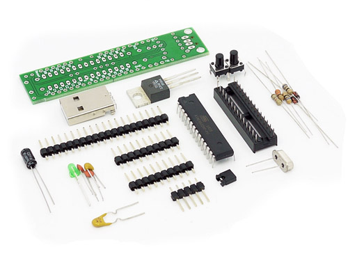
USnooBie Assembly Instructions and Parts Breakup
This is a short version of the official assembly guide, visit the official assembly guide to read more than details.
Assemble the USnooBie according to these steps. The smaller components must be soldered first, before the larger components, this makes associates easier. The parts required are likewise described here and so this document also acts as a office list so you may find replacement components.
 | Two 68 ohm resistorsThese resistors limit the current betwixt the USB device (microcontroller) and the USB host (estimator) on the D+ and D- lines of the USB bus. They act as terminating resistors, so the terminating impedance matches the USB cablevision's characteristic impedance, reducing betoken reflections. They are small and low components and are thus soldered first. These should exist two 68 ohm ane/4 watt +/- 5% tolerance carbon film resistors. | 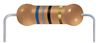 |
 | D- pull-up resistorThis resistor is placed on the D- line of the USB charabanc. When D- is pulled up, it indicates to the USB host that the USB device is a low speed USB ane.1 device. This resistor is usually 2.2 kilo-ohm if pulling up to 5V and 1.5 kilo-ohm when pulling upwardly to three.3V. 1.eight kilo-ohm works well with both 5V and three.3V. This resistor should exist ane i.eight kilo ohm i/iv watt +/- 5% tolerance carbon flick resistor. Note: the original design used a ane.7 kilo ohm resistor, the kit being sold is provided with a one.8 kilo ohm resistor, either should piece of work. The schematics may evidence a 1.7 kilo ohm resistor (typo, deplorable). | 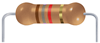 |
 | LED current limit resistorThis resistor limits the electric current for the ability indication LED. If this electric current is non limited, then the LED'due south lifespan is drastically reduced. This resistor should exist a 330 ohm one/4 watt +/- 5% tolerance carbon motion-picture show resistor. | 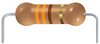 |
 | Two three.6V Zener diodesThese 3.6V Zener diodes ensures that the signal on the D+ and D- lines of the USB bus are inside acceptable limits. This allows the USB device to run at 5V without dissentious other devices on the USB autobus. These should be 1N5227B three.6V Zener diodes. There have been reports that sure Zener diodes will not work. 200mW Zener diodes may non work but 500mW Zener diodes will (source: http://forums.obdev.at/viewtopic.php?f=8&t=4677). Ensure that you identify these parts in the right orientation as indicated by the symbol on the PCB. The triangle on the symbol points in the management which the stripe on the diode should be. | 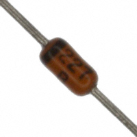 |
 | Reverse electric current protection diodeThis part is not included in the kit provided past Seeed Studio. You lot must replace this function with a jumper wire or else the USnooBie volition not receive ability from the USB port. | 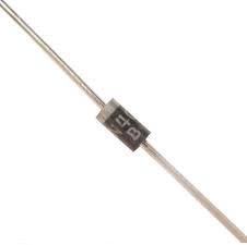 |
 | Power indicator LEDThis LED indicates that there is power on the power bus. Note that it does not bespeak the amount of power, and so even if it is lit, it does not guarantee that sure components are receiving enough voltage. This must exist a 3mm diameter standard LED. This LED may be omitted if you want to save power or you want a "stealthy" USB device. Ensure that you place this part in the correct orientation as indicated by the symbol on the PCB. If you are unable to determine the management of the LED, then you should examination the LED before installing it. The "apartment side" should be the cathode, which should be negative to light upwards, while the "round side" is the anode, which should be positive to light up. Use a 3V money cell bombardment to perform this test really apace to avoid damaging the LED. | 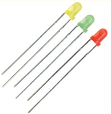 |
 | USB A male connectorThis allows the United statesnooBie to be plugged direct into a USB port, or you can buy a USB extension cable from the dollar store to connect it. | 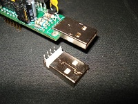 |
 | Two tactile SPST momentary on button switchI button is used to reset the AVR microcontroller, the other button acts as a bootloader activation button. Upon reset, the AVR runs the bootloader section code which checks whether or non the bootloader activation push button is held down. If information technology is held down, the bootloader becomes a USBasp device then you may load your own code into the AVR microcontroller. If information technology is non held down, and so the bootloader jumps to the awarding section to run the code you have previously loaded. This bootloader activation button is placed on the D- line, when pressed during normal use (not during kicking time), information technology will cause the USB device to announced asunder from the USB host. This is useful in certain situations when you require your device to disconnect without physically disconnecting. The Omron B3F-1000 tactile SPST momentarty on push button switch should be used here. | 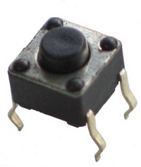 |
 | 28 pin DIP chip socketA 28 pivot DIP flake socket is used to hold the AVR ATmega microcontroller. Due to the placement of the 3 tandum capacitors, a 28 pin DIP flake socket must be used (or 2 14 pin DIP scrap sockets, the PCB layout is designed to permit this) to hold the AVR ATmega microcontroller. The scrap socket should accept a gap down its heart, giving yous room to identify the three capacitors. Solder in the sockets first, and then insert the capacitors through the gap. Run across the movie provided. Ensure that yous place this part in the right orientation equally indicated by the symbol on the PCB. Exercise not insert the chip into the socket until the board passes some unproblematic testing (afterward steps). | 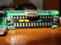 |
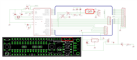
 | Iii monolithic capacitorsThe 0.1uF capacitor is a decoupling capacitor which smooths out fine ripples on the power bus. The lawmaking on this capacitor should be 104 (pregnant 0.1uF). The two 27pF capacitors cleans the signals from the 12 MHz crystal. The code on these capacitor should be 270 (meaning 27 pF). These capacitors can be monolithic or ceramic. | |
 | 12 MHz crystalThe 12 MHz crystal is the clock source for the AVR microcontroller. Information technology is 12 MHz because that'south the best clock speed for 3.3V opertation that is supported past V-USB. The crystal must be a 12 MHz crystal in a HC49 parcel. Depression profile packaging is prefered, equally long as the pin spacing is the aforementioned. | 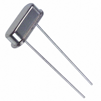 |
 | Voltage option jumperA iii pin header is used to select the voltage on the power bus, a shunt block is used on the iii pivot header to make the connection that makes the selection. This allows you lot to cull between using the 5V power supply from the USB port or using the three.3V power supply provided past the 3.3V voltage regulator. Do not install the jumper shunt block until the board has passed some tests (described in later steps). | 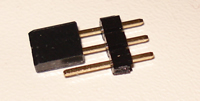 |
 | PTC resettable fuseThis fuse protects the USB host from impairment during short excursion situations by cutting off current. The fuse will estrus up when current reaches unacceptable levels and it will get a resistor, limiting the current drastically, and when the fuse cools down, it loses its resistance and conducts current again. This will protect your estimator if you accidentally short your power bus. Since it resets itself automatically later on cooling downwardly, it volition never need to be replaced (unlike an ordinary fuse). Notation that the USB bus can only supply up to 500mA of current, the fuse provided will build up resistance once it reaches 250mA and cut off power completely if the electric current reaches 500mA. For most applications, this amount of ability is plenty, if you require more power, consider utilizing an external power source every bit the power supply, instead of your figurer. This component should exist the RXE025 from Tyco Electronics, it is the same PTC resettable fuse sold on SparkFun. It has a I-hold of 250mA and I-trip of 500mA. | 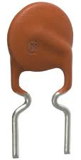 |
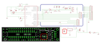 | 4.7 uF electrolytic capacitorThis capacitor smooths out large slow ripples on the power double-decker, and acts every bit a minor reservoir during sudden electric current depict. This should be a 4.7 uF electrolytic capacitor rated at 10 volts in radial packaging. Ensure that yous identify this part in the correct orientation every bit indicated past the symbol on the PCB. The capacitor should accept a strip on the side with negative (minus signs) symbols, which corresponds to the negative side of the capacitor symbol on the PCB (opposite to the pad with the positive + symbol). | 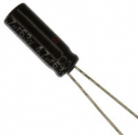 |
 | 3.3V low dropout voltage regulatorThis should exist a TC1262 in TO-220 packaging. It is a low dropout voltage regulator that will pace down the 5V USB ability down to 3.3V. This may exist omitted if you do not desire a iii.3V ability source. Ensure that y'all place this function in the right orientation as indicated by the symbol on the PCB. The metallic heatsink on the voltage regulator should face towards the inside of the board (every bit indicated by the thicker silkscreened line). This component must be a 3.3V low dropout voltage regulator in 3 pin TO-220 packaging. Microchip's TC1262 or similar may be used. | 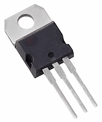 |
 | Male headersThere are three groups of male headers. Ane long group that has 16 pins, two shorter groups with half-dozen pins each. These male person headers let y'all to insert the USnooBie into a breadboard. These headers should go on the bottom of the PCB. To make soldering these header pins easier, you can try inserting them into the breadboard first, so placing the United statesnooBie PCB on top, so that the breadboard keeps the header pins straight and holds them in place for you while you solder from the PCB's top side. | 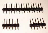 |
 | Continuity testing the basisUse a multimeter'southward continuity tester to cheque that all pins/pads/joints that are supposed to be ground are continued to each other and only each other. If this examination passes, then you should be able to cheque the voltages while powered upwardly without worrying besides much virtually a short causing massive current draw. | |
 | Continuity testing the power busUse a multimeter'south continuity tester to bank check that all pins/pads/joints that are supposed to be on the power bus are connected to each other and but to each other. Do this while the voltage choice jumper shunt block is not installed. | |
 | Voltage checkPlug in the U.s.nooBie into a powered USB port and check the voltages on the pads/pins/joints which are supposed to be 5V. Do the same for the ones that are supposed to be 3.3V. Install the jumper shunt block on to the voltage selection jumper pivot header. Cheque that you are able to select the voltage on the power bus by moving the jumper shunt block. When in that location is power on the power bus, the power indicator LED should besides light upward. | |
 | Insert the microcontrollerInsert the AVR ATmega328P microcontroller into the 28 pivot DIP chip socket to terminate constructing the UsanooBie. If the correct bootloader is already loaded on the microcontroller and the microcontroller's fuse bit settings are correct, y'all tin start to employ the UsnooBie (if you buy it from Seeed Studio, then this is done for you lot already). Follow the instructions for loading code onto the USnooBie to check that it functions every bit a USB device when connected to a computer. | 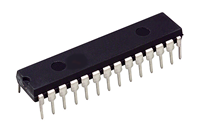 |
Usage Guide
This is the short version of the official usage guide, get visit the official usage guide for more details.
To enter the bootloader, hold down the bootloader-activation push button, then press and release the reset push button, then release the bootloader-activation button. The bootloader should appear to your reckoner as an USBasp programmer, so you may now employ information technology every bit though you were using an USBasp with AVRDUDE.
A typical AVRDUDE command would start with "avrdude -c usbasp -p atmega328p", and to load a hex file into flash memory, information technology looks like "avrdude -c usbasp -p atmega328p -U flash:w:filename.hex". You will not exist able to modify any fuse-$.25, which prevents you lot from "damaging" the bootloader.
In that location's a good chance that you'll require the USBasp drivers in order for the USBaspLoader bootloader to work. The drivers can be found here
Pace iii: Understanding USB
USB uses two wires, unremarkably chosen D+ and D-, to transmit series information using non-return-to-cypher coding. These two wires are a differential pair, meaning D-'south signal will ever be D+'s inverted country. This allows information technology to transfer information really fast over a long cablevision (v meter cable at 480 Mbit/due south if using USB two.0 high speed), read this for more http://en.wikipedia.org/wiki/Differential_pair
USB busses have a device and host, the computer is usually the host, our game pad is a device, more specifically, a HID (human interface device). It is important to note that the host always initiate advice, or the host checks the device frequently to encounter if information technology has anything to say. The device does not have the ability to initiate advice, information technology can only wait until it's spoken to.
There are pull-up resistors on D+ or D- depending on whether or not the device is USB 1.0, USB 1.one, or USB 2.0. The presense of these pull-up resistors is also how a reckoner knows when something has continued. On the USnooBie and most V-USB circuitry, the pull-upwardly resistor is ever on the D- signal since V-USB is only capable of implementing low speed USB devices.
The two 68 ohm resistors on the D+ and D- signals are terminating resistors, their impedance are calculated (taking into account the AVR'south internal circuitry) to be matched with the characteristic impedance of the USB cable. This minimizes signal reflections. Read http://en.wikipedia.org/wiki/Transmission_line to larn more.
When a device connects to a host, the host tries to "enumerate" the device. If it fails to exercise so (device not responding, or responding with garbage), that'southward when Windows says "device non recognized".
The host and device talks over channels called "endpoints", endpoints are identified by a number. There are some endpoints that a reserved for special use, while others can be configured to operate in dissimilar modes (interrupt, bulk, etc).
The host will always first utilise the "control endpoint" (endpoint 0) beginning to request a description of the device, this "descriptor" will contain the device identifiers (vendor ID and production ID, etc), along with its device class, bracket, etc (HID like a mouse or keyboard? or mayhap mass storage?). Then the configuration descriptor is requested, which also contains the number of endpoints available on the device. Each endpoint has its ain descriptor as well. All of this information are sent as packets of information bytes representing a well known specified information construction.
V-USB and other USB frameworks/stacks have APIs and other methods to permit the programmer to change the content in the descriptors. Yous demand to showtime understand each descriptor, and and so cheque the documentation on Five-USB to meet how to change them (I'll show you lot afterward).
The host makes the requests by sending "setup packets" to the "control endpoint". Setup packets accept a defined structure making it easy for the device to empathise what the host wants. 5-USB (and similar frameworks) normally handles the default setup packets. A programmer can write drivers that sends custom setup packets, in which instance the firmware must handle the setup packets manually, 5-USB (and others) provides some methods to assist with that.
Later on in this instructable, I have included a dump of the descriptors captured by my USB traffic analyzer. You can take a await and friction match it upwards with USB specifications to see what each portion represents.
Once all the descriptors have been retrieved from the device, the host tin can and so sympathise the device and communicate with information technology. We'll look at all the descriptors in item later.
I have another Instructable which shows you how to build a USB keyboard that types out the code stored in RFID tags: https://world wide web.instructables.com/id/USB-RFID-Reading-Keyboard/
Homework: Read USB in a Nutshell http://www.beyondlogic.org/usbnutshell/usb1.shtml which is pretty much a USB bible
Important Note: Most of the USB terminology is from the perspective of the host (the computer), so the words "in" and "input" means from the device to the host, and the words "out" or "output" mean from the host to device.
Pace 4: USB Descriptors
Hither'south the USB in a Nutshell page on descriptors, you need to refer to this some times.
To recap, we need to worry about the device descriptor, configuration descriptor, interface descriptor, endpoint descriptor, and string descriptors. In that location is as well a USB Homo Interface Device Report Descriptor that we will demand to write later.
The device descriptor will tell the computer information about the device in full general. Info such as the USB standard it meets, information technology's device course & device subclass, protocol, vendor, production ID, and a few optional strings such as product name, manufacture proper name, and serial number. Information technology will likewise point how many configurations there are available for this device (this is near ever just one).
For this project, the device class is set to 0, meaning "defer to interface", so our interface descriptor will describe this device as a Human Interface Device (HID). The device subclass and protocol are irrelevant. The vendor ID and product ID tin can be anything (sort of, we'll talk about this afterward). In the source code, I've set the manufacture string to my website, and the proper noun of the device is "Wii Pad".
Each configuration descriptor will signal how the device is powered, how much power it needs, and how many interfaces it has. There is also a string that describes each configuration (I haven't seen this used). Unlike configuration can be selected but unremarkably there is merely one available configuration.
For this project, the configuration will indicate that this gamepad will exist powered by the USB port and it volition need about 100 mA of current (no information technology doesn't, but 100 is a nice number and well over our real requirements). In that location is just ane interface.
Each interface descriptor contains info virtually the number of endpoints in the interface, and so the interface class, interface subclass, and interface protocol of this particular interface.
For this project, we will be using endpoint #0, which is the "control endpoint" (default for standard requests from the figurer), and endpoint #1, which is a "interrupt-in" endpoint that nosotros'll be sending USB HID reports (these reports contain the gamepad information) through. The class will be 0x03, indicating Man Interface Device (HID), the bracket and protocol are both 0x00.
More Reading:
- http://www.beyondlogic.org/usbnutshell/usb5.shtml#DeviceDescriptors
- http://en.wikipedia.org/wiki/USB_human_interface_device_class
- http://world wide web.usb.org/developers/devclass_docs/HID1_11.pdf
- http://world wide web.usb.org/developers/hidpage/
- http://www.usb.org/developers/
Step 5: USB HID Reports and Report Descriptors
When you make a HID device, the device sends short reports at regular intervals to the computer. These reports contain data about which buttons are pressed and how much the joysticks have moved. However, in gild for the host to understand the data format, the device must "depict" the reports to the host. This is why we write a USB HID report descriptor.
Take a look at your Wii Classic Controller. It has 15 buttons (round up to 16 for simplicity), and 2 joysticks. This ways we demand to send 15 bits of data for the buttons, and 4 numbers, one for each centrality of joystick data. We define our data format to look like this:
| Bit seven | Fleck 6 | Bit 5 | Bit 4 | Bit 3 | Bit 2 | Bit 1 | Scrap 0 | |
| Byte 0 | Button | Push button | Push button | Push button | Push button | Button | Push button | Button |
| Byte 1 | Push | Push | Push button | Push | Push | Button | Push | Button |
| Byte 2 | Left Stick Ten Centrality as Signed Char Integer | |||||||
| Byte 3 | Left Stick Y Axis every bit Signed Char Integer | |||||||
| Byte 4 | Right Stick X Axis as Signed Char Integer | |||||||
| Byte v | Right Stick Y Centrality every bit Signed Char Integer | |||||||
And then we can ascertain a data construction in C/C++
struct gamepad_report_t { uint16_t buttons; int8_t left_x; int8_t left_y; int8_t right_x; int8_t right_y; } Writing a report descriptor involves describing a usage context first, and then describing the significant of the data relative to the usage context, and so describing the data in terms of its range and size.
Showtime, make the computer empathise that the device is a gamepad
USAGE_PAGE (Generic Desktop) USAGE (Game Pad) Collection (Application) Collection (Concrete) ... Cease Collection End COLLECTION
Then depict the button data (16 $.25)
USAGE_PAGE (Button) USAGE_MINIMUM (Button 1) USAGE_MAXIMUM (Button sixteen) LOGICAL_MINIMUM (0) LOGICAL_MAXIMUM (ane) REPORT_COUNT (16) REPORT_SIZE (1) INPUT (Data,Var,Abs)
Then draw the 4 axis information as signed 8-bit integers
USAGE_PAGE (Generic Desktop) USAGE (X) USAGE (Y) USAGE (Z) USAGE (Rx) LOGICAL_MINIMUM (-127) LOGICAL_MAXIMUM (127) REPORT_SIZE (8) REPORT_COUNT (4) INPUT (Data,Var,Abs)
- NOTE: Z is used to represent the right stick's Ten axis, Rx is used to represent the right stick's Y centrality. This doesn't make sense but this is how most existing USB game pads work. I accept tested this using Battlefield Bad Visitor ii, it works.
- Annotation: Employ "absolute" for something like joysticks, but "relative" for things similar mouse.
Finally, the report descriptor looks similar:
USAGE_PAGE (Generic Desktop) USAGE (Game Pad) Drove (Application) COLLECTION (Physical) USAGE_PAGE (Push button) USAGE_MINIMUM (Button 1) USAGE_MAXIMUM (Button sixteen) LOGICAL_MINIMUM (0) LOGICAL_MAXIMUM (1) REPORT_COUNT (16) REPORT_SIZE (1) INPUT (Data,Var,Abs) USAGE_PAGE (Generic Desktop) USAGE (X) USAGE (Y) USAGE (Z) USAGE (Rx) LOGICAL_MINIMUM (-127) LOGICAL_MAXIMUM (127) REPORT_SIZE (8) REPORT_COUNT (4) INPUT (Information,Var,Abs) END COLLECTION END Collection
At present that we take a report descriptor, how do we make our AVR tell this stuff to the computer? Go download the official "HID Descriptor Tool" from http://www.usb.org/developers/hidpage/ . Use it to put this stuff in, and the tool will generate the correct binary array for yous.


When you relieve your result, go to "File" -> "Save As", and then make certain you choose "Header File (*.h)" in the save dialog. Then open the file, it should await like
char ReportDescriptor[ some number hither (size of array)] { a lot of bytes here }; Dandy, the size of array needs to be copied into 5-USB's "usbconfig.h" where information technology says "USB_CFG_HID_REPORT_DESCRIPTOR_LENGTH", and "char ReportDescriptor" needs to be renamed to "PROGMEM char usbHidReportDescriptor" then that it is stored into the AVR'southward flash retention. You lot stop upwardly with something similar:
PROGMEM char usbHidReportDescriptor[46] = { 0x05, 0x01, // USAGE_PAGE (Generic Desktop) 0x09, 0x05, // USAGE (Game Pad) 0xa1, 0x01, // Collection (Application) 0xa1, 0x00, // COLLECTION (Physical) 0x05, 0x09, // USAGE_PAGE (Button) 0x19, 0x01, // USAGE_MINIMUM (Button 1) 0x29, 0x10, // USAGE_MAXIMUM (Button 16) 0x15, 0x00, // LOGICAL_MINIMUM (0) 0x25, 0x01, // LOGICAL_MAXIMUM (1) 0x95, 0x10, // REPORT_COUNT (16) 0x75, 0x01, // REPORT_SIZE (ane) 0x81, 0x02, // INPUT (Data,Var,Abs) 0x05, 0x01, // USAGE_PAGE (Generic Desktop) 0x09, 0x30, // USAGE (Ten) 0x09, 0x31, // USAGE (Y) 0x09, 0x32, // USAGE (Z) 0x09, 0x33, // USAGE (Rx) 0x15, 0x81, // LOGICAL_MINIMUM (-127) 0x25, 0x7f, // LOGICAL_MAXIMUM (127) 0x75, 0x08, // REPORT_SIZE (viii) 0x95, 0x04, // REPORT_COUNT (iv) 0x81, 0x02, // INPUT (Information,Var,Abs) 0xc0, // END_COLLECTION 0xc0 // END_COLLECTION }; That piece of lawmaking, plus the struct typedef nosotros did earlier, is included in our projection source code (come across whole source lawmaking) later.
More Reading:
- http://www.usb.org/developers/devclass_docs/HID1_11.pdf
- http://www.usb.org/developers/hidpage
- http://www.frank-zhao.com/index.php?page=hid_tutorial_1
Step 6: Handling USB Standard Requests
The host will eventually send some requests to our device, perchance to request a descriptor, the study, or set some parameters (notably, the "idle rate").
Each request comes in a standard format, which can be mapped to a information structure that describes the request in terms of its size, meaning, and contents. Information technology looks like:
typedef struct usbRequest{ uchar bmRequestType; uchar bRequest; usbWord_t wValue; usbWord_t wIndex; usbWord_t wLength; }usbRequest_t; 5-USB's API requires you to make a function chosen "usbFunctionSetup" which takes 8 bytes in. These eight bytes are casted to the type "usbRequest_t". And then, the request is decoded and fulfilled. There are 3 things we must handle:
- Asking for the report
- Request for the report descriptor
- Request to set the idle charge per unit
So the piece of lawmaking looks similar:
static unsigned char idleRate; unsigned char usbFunctionSetup(unsigned char data[viii]) { usbRequest_t *rq = (void *)data; if ((rq->bmRequestType & USBRQ_TYPE_MASK) == USBRQ_TYPE_CLASS) /* form request type */ { if (rq->bRequest == USBRQ_HID_GET_REPORT) /* wValue: ReportType (highbyte), ReportID (lowbyte) */ { usbMsgPtr = &gamepad_report; return sizeof(gamepad_report); } else if (rq->bRequest == USBRQ_HID_GET_IDLE) { usbMsgPtr = &idleRate; return i; } else if (rq->bRequest == USBRQ_HID_SET_IDLE) { idleRate = rq->wValue.bytes[1]; } } else { // no vendor specific requests implemented } return 0; } This piece of lawmaking goes into the whole source code.
More Reading:
- http://www.usb.org/developers/devclass_docs/HID1_11.pdf
- http://www.usb.org/developers/hidpage
- http://www.beyondlogic.org/usbnutshell/usb4.shtml#Control
- http://vusb.wikidot.com/driver-api
Pace 7: Connecting the Wii Classic Controller
Since you exercise non desire to cutting the cable on your Wii Classic Controller, go purchase a cheap extension cable for Wiimote accessories. These have a female person connector that you will demand to cut off. Strip the outer coating of the extension cable to access the wires inside.
For prototyping purposes, I have soldered the wires to a male header.
Note that the device-detection wire on the cheap extension cables practise not actually work (they are connected directly to +iii.3V), thus I am unable to truly detect a device-connect or disconnect event in the software.
The signals are:
- Ground, connect to ground on the USnooBie
- +3.3V ability supply, connect to USnooBie's +iii.3V pin
- SDA (this is the I2C data line), connect to PC4 on USnooBie
- SCL (I2C clock line), connect to PC5 on USnooBie
Brand certain that USnooBie is supplied with three.3V by using the voltage option jumper. This is so that the internal pull-up resistors (on the I2C lines) of the ATmega328P will use three.3V instead of 5V. Too the Wii Classic Controller must be powered with 3.3V as well.
Step 8: TWI / I2C Explained
I2C stands for Inter-Integrated Circuit. I2C busses are as well known every bit TWI for Two Wire Interface, since it uses just two wires.
Related Readings:
- http://en.wikipedia.org/wiki/I%C2%B2C
- I2C Tutorial - Embedded Labs
- https://www.instructables.com/id/music-playing-warning-clock/step22 < my other instructable that explains I2C
On a TWI passenger vehicle, the ii signal wires are SDA and SCL, basically information and clock. These signals are open drain (meaning its logic level is either high impedance or low, it cannot always be loftier), merely there must be a pull-upwards resistor on each of these signals (nosotros are using the AVR's internal pull-up resistors). This is pregnant because any device on a TWI omnibus can drive the signals low at whatever time, so the signal can only become high when all the devices allow it to become loftier. This allows devices to detect when the bus is occupied ("arbitration using SDA") and also allow a deadening device to dictate the speed of the clock, or fifty-fifty interruption a transmission if the slower device is besides decorated (doing this is called "clock stretching". These facts makes the TWI bus practiced for communication between a agglomeration of chips using just two wires.
Every transaction is between a master (the one driving the clock signal) and a slave device. Every transaction starts with a "start condition" and ends with a "end condition". A showtime condition is when the bus master drives SDA low first, then driving SCL low 2d. An stop status is when the master releases the TWI bus past releasing SCL and and then releasing SDA.
Subsequently the start condition, the main has to choose which device to talk to by sending a seven bit address byte. The 8th (final being sent) chip indicates whether or not the master wishes to read (1) from or write (0) to the slave being addressed. If the master is writing, information technology will then transport more than data. If the master is reading, it will release the SDA line so the slave sends information (but the master is still driving the clock). When addressed
All bytes are sent MSB offset (most significant bit kickoff). Every byte is optionally ended by an acknowledgement/nacknowledgement. Check the device datasheet to see what the device will expect or will send back. Usually, to quote Wikipedia: "If the master wishes to write to the slave then it repeatedly sends a byte with the slave sending an ACK scrap. (In this situation, the master is in master transmit mode and the slave is in slave receive mode.) If the primary wishes to read from the slave then it repeatedly receives a byte from the slave, the master sending an ACK bit after every byte only the last one. (In this situation, the master is in primary receive manner and the slave is in slave transmit style.)"
More intricate details are usually specific to a particular device, and such information volition come from its datasheet.
When I apply I2C/TWI with AVR microcontrollers, I use the depression level layer of the "Wire" library for Arduino. The Wire library is the C++ wrapper for the lower level "twi.c" and "twi.h" module, which I modify slighly and compile into my own code (since I don't usually employ C++). Information technology takes care of near everything.
The Wii Classic Controller has a I2C address of 0x52, continue that in listen. Using "twi.c" and "twi.h", to send some data to the Wii Classic Controller, start by creating a byte array containing the data to be sent, and then laissez passer that to the "twi_writeTo" role, along with the destination address, the amount of data to ship, and tell it "expect until all information is sent". The code will look like:
unsigned char dataArray[3] = { 'a', 'b', 'c', }; twi_writeTo(0x52, dataArray, three, 1); To read three bytes, use the function "twi_readFrom", and tell information technology the address, the information is saved to a array y'all pass in, and you specify the amount of data. The lawmaking looks like:
unsigned char dataArray[iii]; twi_readFrom(0x52, dataArray, 3);
Pace ix: Reading the Wii Classic Controller
The Wii Classic Controller has an accost of 0x52, which must be specified as the first byte of all I2C transmissions so it knows that it'due south being spoken to.
In our project source lawmaking, we initialize the Wii Classic Controller past:
- Initializing the TWI/I2C module of the AVR, enabling the pull-upwards resistors
- Sending it 0x40 0x00
- Sending it a sequence of fake encryption keys, then the decryption is easy
The data traveling on the bus later this initialization have been performed volition nonetheless be encrypted, but since nosotros've just gave it the fake keys, we know exactly how to decrypt information technology. Run across source code for details.
In the main loop of the lawmaking, data is read from the Wii Classic Controller by
- Sending it 0x00, this sets a read arrow
- Reading half-dozen bytes of data from information technology
Here'southward the data format for the 6 bytes of data that we read from the Wii Archetype Controller:
| Bit | ||||||||
| Byte | vii | 6 | 5 | 4 | three | 2 | one | 0 |
| 0 | RX <iv:3> | Threescore <5:0> | ||||||
| i | RX <2:ane> | LY <5:0> | ||||||
| 2 | RX <0> | LT <4:3> | RY <4:0> | |||||
| iii | LT <ii:0> | RT <4:0> | ||||||
| 4 | B DR | B DD | B LT | B - | B H | B + | B RT | 1 |
| 5 | B ZL | B B | B Y | B A | B X | B ZR | B DL | B DU |
LX,LY are the left Analog Stick X and Y (0-63), RX and RY are the right Analog Stick X and Y (0-31), and LT and RT are the Left and Correct Triggers (0-31). The left Analog Stick has twice the precision of the other analog values.
BD{L,R,U,D} are the D-Pad management buttons. B{ZR,ZL,A,B,10,Y,+,H,-} are the discrete buttons. B{LT,RT} are the digital button click of LT and RT. All buttons are 0 when pressed.
Credit to http://wiibrew.org/wiki/Wiimote/Extension_Controllers for this valuable information.
In our project, the data format must exist sent through USB in this format:
| Flake 7 | Chip half dozen | Fleck five | Bit 4 | Bit 3 | Scrap 2 | Bit 1 | Bit 0 | |
| Byte 0 | Button | Push | Button | Button | Button | Button | Button | Button |
| Byte i | Button | Push button | Button | Button | Push | Push | Button | Button |
| Byte 2 | Left Stick X Axis as Signed Char Integer | |||||||
| Byte iii | Left Stick Y Axis as Signed Char Integer | |||||||
| Byte 4 | Right Stick X Axis as Signed Char Integer | |||||||
| Byte 5 | Right Stick Y Axis as Signed Char Integer | |||||||
Our source code does a bit of unproblematic binary math to perform the transformation. Note that buttons needs to be 1 when pressed and so nosotros invert the button information from the Wii Classic Controller.
When the microcontroller starts up, it besides takes a reference center reading for the joysticks to calibrate it, this middle value is combined with a depression-pass-filtered showtime to eliminate noisy readings.
See the whole source code for more details.
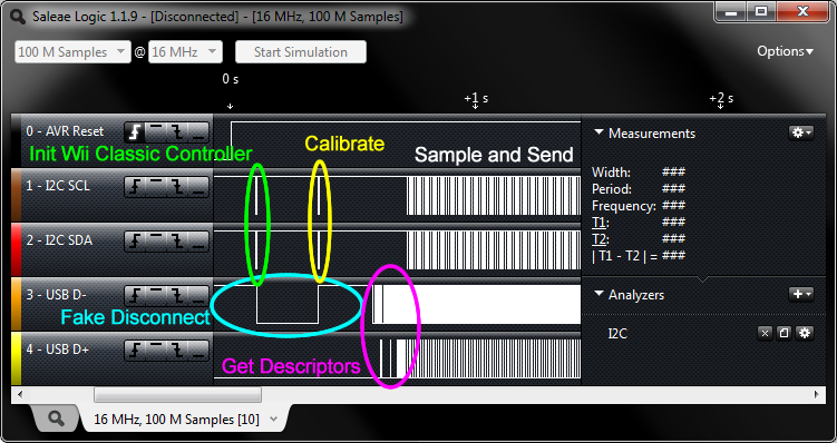
I've also attached a logic analyzer session file ( .logicsession file, can be viewed with Saleae Logic 1.1.9), and a text format log file of I2C communications with the Wii Classic Controller. You can download these and study the advice in-depth.
Step 10: Compiling and Loading the Code
The project can be opened with AVR Studio 5 or AVR-Project-IDE, open it and build the project. The hex file that is generated can be loaded into the ATmega328P using AVRDUDE.
If you lot are using the USnooBie, then yous can follow this guide:
Usage Guide
This is the short version of the official usage guide, go visit the official usage guide for more than details.
To enter the bootloader, concord downwardly the bootloader-activation push button, then printing and release the reset button, so release the bootloader-activation button. The bootloader should appear to your computer equally an USBasp programmer, then you may now use it as though you lot were using an USBasp with AVRDUDE.
A typical AVRDUDE command would start with "avrdude -c usbasp -p atmega328p", and to load a hex file into flash retentiveness, it looks like "avrdude -c usbasp -p atmega328p -U wink:w:filename.hex". Yous volition non exist able to modify whatsoever fuse-bits, which prevents you from "damaging" the bootloader.
In that location's a skilful gamble that you'll crave the USBasp drivers in order for the USBaspLoader bootloader to work. The drivers can be found here
Step xi: Finishing Up
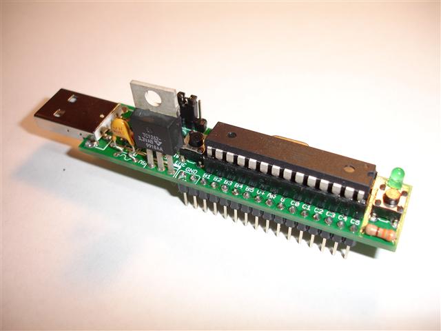
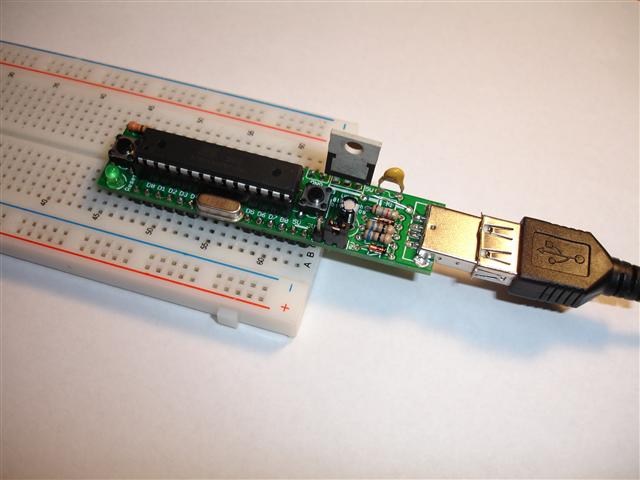
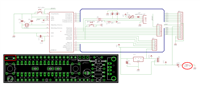
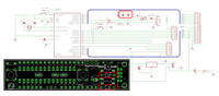
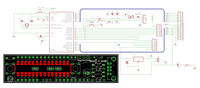
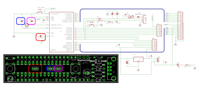
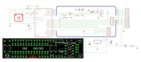
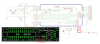
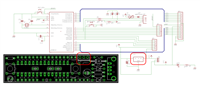
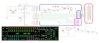
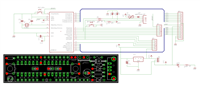
I purchased a small plastic enclosure, and a prototyping excursion lath. In the front end of the enclosure, I cutting a hole for the USB connector and the Wii extension connector. I glued the Wii extension connector into the correct location on the circuit board and soldered the wires to the excursion board. I replicated the USnooBie circuitry onto the circuit lath. The circuit board is then mounted into the enclosure. This created a bully final finished product.
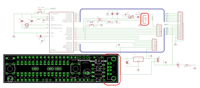
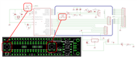
To replicate the circuit, encounter the downloads page for USnooBie, it's open source and all the schematic and PCB files are bachelor.
This step is optional, depending on how much coin yous want to spend.
Footstep 12: Testing and Using
Plug it in and it should cause your operating organisation to automatically install the drivers required. If the vendor ID and product ID is causing problems (conflicts with older drivers, etc), go alter them in "usbconfig.h", recompile the project, and re-program the AVR with the new recompiled hex file.
Do not disconnect the Wii Archetype Controller from the excursion while it is plugged into USB. If you exercise, you might need to disconnect and reconnect the USB cable in order to force a reset. This is because the cheap extension cable connector does not allow me to implement device detection properly. In the source code, I'chiliad depending on the lookout man-canis familiaris timer to automatically perform this reconnection, the watchdog timer will timeout in the TWI part while waiting for the rely from the Wii Archetype Controller and cause the reset, which causes the false reconnection.
Open up up the joystick thing in Window's control panel and watch it work.
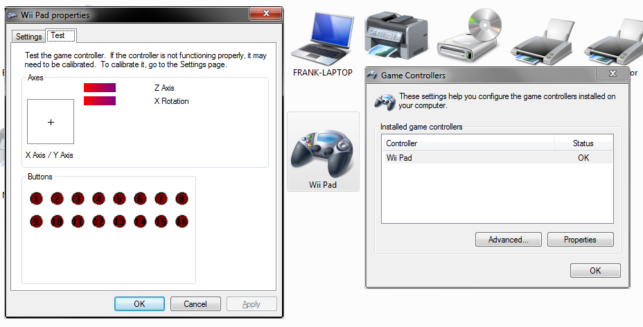
If you want to employ information technology in a video game, be sure to map all the buttons first.
If a joystick centrality is inverted, then y'all can go into the source code and multiply its value by negative one. In fact, you can do a lot of creative things in the source code! You can add scaling to the joysticks, or rapid tapping behaviour to the buttons if you want.
Step xiii: Bonus: Keyboard and Mouse
By modifying the HID report descriptors slightly, we can likewise turn this project into a USB keyboard or USB mouse, or a combination device. I have fastened all of the source code.
USB Mouse
The HID report descriptor has been modified to point that the usage is a mouse arrow. The X and Y movements are now relative instead of accented. There are only three $.25 used for the mouse buttons (left click, correct click, center click), there is as well vertical mouse wheel scrolling, and horizontal scrolling (doesn't really piece of work without Logitech drivers, as information technology'south non a standard feature).
The data structure becomes something similar this:
| Bit 7 | Scrap 6 | Scrap 5 | Bit 4 | Scrap 3 | Scrap 2 | Bit 1 | Chip 0 | |
| Byte 0 | Useless | Useless | Useless | Useless | Useless | Heart Push button | Left Button | Right Button |
| Byte i | X Axis Relative Motility as Signed Integer | |||||||
| Byte 2 | Y Axis Relative Movement every bit Signed Integer | |||||||
| Byte 3 | Vertical Curl as Signed Integer | |||||||
| Byte 4 | Horizontal Scroll as Signed Integer | |||||||
The corresponding C information struct looks similar:
static struct mouse_report_t { uint8_t buttons; // button mask ( . . . . . Yard L R ) int8_t 10; // mouse ten move int8_t y; // mouse y motion int8_t v_wheel; // mouse wheel move int8_t h_wheel; // mouse bicycle movement } mouse_report; The HID report descriptor looks like
PROGMEM char usbHidReportDescriptor[61] = { // make certain the size matches USB_CFG_HID_REPORT_DESCRIPTOR_LENGTH in usbconfig.h 0x05, 0x01, // USAGE_PAGE (Generic Desktop) 0x09, 0x02, // USAGE (Mouse) 0xa1, 0x01, // Drove (Application) 0x09, 0x01, // USAGE (Pointer) 0xa1, 0x00, // Collection (Physical) 0x05, 0x09, // USAGE_PAGE (Push button) 0x19, 0x01, // USAGE_MINIMUM (Button 1) 0x29, 0x03, // USAGE_MAXIMUM (Button three) 0x15, 0x00, // LOGICAL_MINIMUM (0) 0x25, 0x01, // LOGICAL_MAXIMUM (1) 0x95, 0x03, // REPORT_COUNT (three) 0x75, 0x01, // REPORT_SIZE (one) 0x81, 0x02, // INPUT (Data,Var,Abs) 0x95, 0x01, // REPORT_COUNT (ane) 0x75, 0x05, // REPORT_SIZE (5) 0x81, 0x03, // INPUT (Cnst,Var,Abs) 0x05, 0x01, // USAGE_PAGE (Generic Desktop) 0x09, 0x30, // USAGE (Ten) 0x09, 0x31, // USAGE (Y) 0x09, 0x38, // USAGE (Wheel) 0x15, 0x81, // LOGICAL_MINIMUM (-127) 0x25, 0x7f, // LOGICAL_MAXIMUM (127) 0x75, 0x08, // REPORT_SIZE (8) 0x95, 0x03, // REPORT_COUNT (3) 0x81, 0x06, // INPUT (Data,Var,Rel) 0x05, 0x0c, // USAGE_PAGE (Consumer Devices) 0x0a, 0x38, 0x02, // USAGE (Undefined) 0x95, 0x01, // REPORT_COUNT (1) 0x81, 0x06, // INPUT (Information,Var,Rel) 0xc0, // END_COLLECTION 0xc0 // END_COLLECTION }; Some minor changes were fabricated in "usbconfig.h", mainly the vendor and production IDs were changed to clone a Logitech make mouse. The production and manufacture strings were changed but this does not have effect in Windows due to the fact that Windows update finds the product data from Windows Update. The length of the HID study descriptor is as well changed to match the size of the array.
USB Keyboard
The HID report descriptor has been modified to betoken that the usage is a keyboard. This descriptor is slightly more complicated. We send 8 bytes of data, the first byte is a modifier byte containing flake flags for the shift, CTRL, ALT, and other modifier keys. The 2nd byte is useless. The last 6 bytes comprise primal codes (non ASCII) of the keys being pressed.
The C data struct looks like:
static struct keyboard_report_t { uint8_t modifier; // bit flags for shift, ctrl, and alt, and other stuff uint8_t reserved; // useless for now uint8_t fundamental[vi]; // HID keycodes } keyboard_report; The HID report descriptor looks like
PROGMEM char usbHidReportDescriptor[63] = { // brand sure the size matches USB_CFG_HID_REPORT_DESCRIPTOR_LENGTH in usbconfig.h 0x05, 0x01, // USAGE_PAGE (Generic Desktop) 0x09, 0x06, // USAGE (Keyboard) 0xa1, 0x01, // COLLECTION (Application) 0x05, 0x07, // USAGE_PAGE (Keyboard) 0x19, 0xe0, // USAGE_MINIMUM (Keyboard LeftControl) 0x29, 0xe7, // USAGE_MAXIMUM (Keyboard Right GUI) 0x15, 0x00, // LOGICAL_MINIMUM (0) 0x25, 0x01, // LOGICAL_MAXIMUM (1) 0x75, 0x01, // REPORT_SIZE (1) 0x95, 0x08, // REPORT_COUNT (8) 0x81, 0x02, // INPUT (Data,Var,Abs) 0x95, 0x01, // REPORT_COUNT (1) 0x75, 0x08, // REPORT_SIZE (8) 0x81, 0x03, // INPUT (Cnst,Var,Abs) 0x95, 0x05, // REPORT_COUNT (5) 0x75, 0x01, // REPORT_SIZE (1) 0x05, 0x08, // USAGE_PAGE (LEDs) 0x19, 0x01, // USAGE_MINIMUM (Num Lock) 0x29, 0x05, // USAGE_MAXIMUM (Kana) 0x91, 0x02, // OUTPUT (Data,Var,Abs) 0x95, 0x01, // REPORT_COUNT (1) 0x75, 0x03, // REPORT_SIZE (3) 0x91, 0x03, // OUTPUT (Cnst,Var,Abs) 0x95, 0x06, // REPORT_COUNT (half dozen) 0x75, 0x08, // REPORT_SIZE (8) 0x15, 0x00, // LOGICAL_MINIMUM (0) 0x25, 0x65, // LOGICAL_MAXIMUM (101) 0x05, 0x07, // USAGE_PAGE (Keyboard) 0x19, 0x00, // USAGE_MINIMUM (Reserved (no event indicated)) 0x29, 0x65, // USAGE_MAXIMUM (Keyboard Application) 0x81, 0x00, // INPUT (Data,Ary,Abs) 0xc0 // END_COLLECTION }; This descriptor is sort of "standardized" so that information technology works without an operating organisation. "usbconfig.h" contains some changes to the interface bracket and protocol to enable "kick protocol" so that it works without an operating system (such as when yous are in BIOS menus).
A V-USB office chosen "usbFunctionWrite" is too created to handle the situation when the computer wants to tell the keyboard to turn on or off status LEDs, such equally the CAPS LOCK, NUM LOCK, or Curlicue LOCK. The function is written but it doesn't actually exercise anything.
// data from the computer is handled here // this is actually going to exist stuff similar NUM LOCK, CAPS LOCK, and SCROLL LOCK LED data unsigned char usbFunctionWrite(unsigned char *data, unsigned char len) { // ignore this information render len; } The function "usbFunctionSetup" is a petty longer to handle some more stuff such every bit changing the electric current protocol, and calling "usbFunctionWrite".
Some other minor changes were made in "usbconfig.h", mainly the vendor and production IDs were inverse. The length of the HID report descriptor is besides changed to match the size of the array.
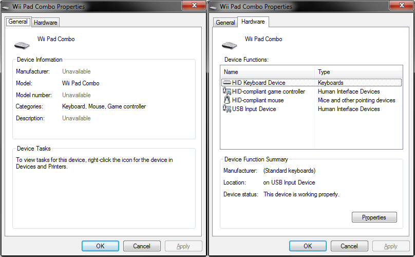
USB Combo Device
I know how to write the descriptor and information structures for a USB combination device (all-in-ane keyboard-mouse-gamepad) but the functioning is kind of bad. Yet, it does sort of work.
The trick is using "Study ID" inside collections of the descriptor. Each collection represents a different device with a unique ID. The ID is sent at the top of each written report. So the descriptor looks similar this (actually long):
PROGMEM char usbHidReportDescriptor[176] = { // brand sure the size matches USB_CFG_HID_REPORT_DESCRIPTOR_LENGTH in usbconfig.h // kickoff of keyboard report descriptor 0x05, 0x01, // USAGE_PAGE (Generic Desktop) 0x09, 0x06, // USAGE (Keyboard) 0xa1, 0x01, // Collection (Application) 0x85, 0x01, // REPORT_ID (1) 0x05, 0x07, // USAGE_PAGE (Keyboard) 0x19, 0xe0, // USAGE_MINIMUM (Keyboard LeftControl) 0x29, 0xe7, // USAGE_MAXIMUM (Keyboard Right GUI) 0x15, 0x00, // LOGICAL_MINIMUM (0) 0x25, 0x01, // LOGICAL_MAXIMUM (i) 0x75, 0x01, // REPORT_SIZE (i) 0x95, 0x08, // REPORT_COUNT (8) 0x81, 0x02, // INPUT (Data,Var,Abs) 0x95, 0x01, // REPORT_COUNT (1) 0x75, 0x08, // REPORT_SIZE (8) 0x81, 0x03, // INPUT (Cnst,Var,Abs) 0x95, 0x05, // REPORT_COUNT (five) 0x75, 0x01, // REPORT_SIZE (i) 0x05, 0x08, // USAGE_PAGE (LEDs) 0x19, 0x01, // USAGE_MINIMUM (Num Lock) 0x29, 0x05, // USAGE_MAXIMUM (Kana) 0x91, 0x02, // OUTPUT (Information,Var,Abs) 0x95, 0x01, // REPORT_COUNT (ane) 0x75, 0x03, // REPORT_SIZE (3) 0x91, 0x03, // OUTPUT (Cnst,Var,Abs) 0x95, 0x06, // REPORT_COUNT (vi) 0x75, 0x08, // REPORT_SIZE (8) 0x15, 0x00, // LOGICAL_MINIMUM (0) 0x25, 0x65, // LOGICAL_MAXIMUM (101) 0x05, 0x07, // USAGE_PAGE (Keyboard) 0x19, 0x00, // USAGE_MINIMUM (Reserved (no result indicated)) 0x29, 0x65, // USAGE_MAXIMUM (Keyboard Awarding) 0x81, 0x00, // INPUT (Data,Ary,Abs) 0xc0, // END_COLLECTION // outset of mouse report descriptor 0x05, 0x01, // USAGE_PAGE (Generic Desktop) 0x09, 0x02, // USAGE (Mouse) 0xa1, 0x01, // Drove (Awarding) 0x09, 0x01, // USAGE (Pointer) 0xa1, 0x00, // Drove (Physical) 0x85, 0x02, // REPORT_ID (2) 0x05, 0x09, // USAGE_PAGE (Button) 0x19, 0x01, // USAGE_MINIMUM (Button 1) 0x29, 0x03, // USAGE_MAXIMUM (Push 3) 0x15, 0x00, // LOGICAL_MINIMUM (0) 0x25, 0x01, // LOGICAL_MAXIMUM (1) 0x95, 0x03, // REPORT_COUNT (three) 0x75, 0x01, // REPORT_SIZE (1) 0x81, 0x02, // INPUT (Data,Var,Abs) 0x95, 0x01, // REPORT_COUNT (1) 0x75, 0x05, // REPORT_SIZE (five) 0x81, 0x03, // INPUT (Cnst,Var,Abs) 0x05, 0x01, // USAGE_PAGE (Generic Desktop) 0x09, 0x30, // USAGE (X) 0x09, 0x31, // USAGE (Y) 0x09, 0x38, // USAGE (Wheel) 0x15, 0x81, // LOGICAL_MINIMUM (-127) 0x25, 0x7f, // LOGICAL_MAXIMUM (127) 0x75, 0x08, // REPORT_SIZE (viii) 0x95, 0x03, // REPORT_COUNT (iii) 0x81, 0x06, // INPUT (Data,Var,Rel) 0x05, 0x0c, // USAGE_PAGE (Consumer Devices) 0x0a, 0x38, 0x02, // USAGE (Undefined) 0x95, 0x01, // REPORT_COUNT (one) 0x81, 0x06, // INPUT (Information,Var,Rel) 0xc0, // END_COLLECTION 0xc0, // END_COLLECTION // start of gamepad report descriptor 0x05, 0x01, // USAGE_PAGE (Generic Desktop) 0x09, 0x05, // USAGE (Game Pad) 0xa1, 0x01, // Collection (Application) 0xa1, 0x00, // COLLECTION (Concrete) 0x85, 0x03, // REPORT_ID (iii) 0x05, 0x09, // USAGE_PAGE (Button) 0x19, 0x01, // USAGE_MINIMUM (Push i) 0x29, 0x10, // USAGE_MAXIMUM (Button 16) 0x15, 0x00, // LOGICAL_MINIMUM (0) 0x25, 0x01, // LOGICAL_MAXIMUM (1) 0x95, 0x10, // REPORT_COUNT (16) 0x75, 0x01, // REPORT_SIZE (1) 0x81, 0x02, // INPUT (Data,Var,Abs) 0x05, 0x01, // USAGE_PAGE (Generic Desktop) 0x09, 0x30, // USAGE (X) // left Ten 0x09, 0x31, // USAGE (Y) // left Y 0x09, 0x32, // USAGE (Z) // right X 0x09, 0x33, // USAGE (Rx) // right Y 0x15, 0x81, // LOGICAL_MINIMUM (-127) 0x25, 0x7f, // LOGICAL_MAXIMUM (127) 0x75, 0x08, // REPORT_SIZE (eight) 0x95, 0x04, // REPORT_COUNT (4) 0x81, 0x02, // INPUT (Data,Var,Abs) 0xc0, // END_COLLECTION 0xc0 // END_COLLECTION }; And the structures now include a report ID:
static struct keyboard_report_t { uint8_t report_id; uint8_t modifier; // bit flags for shift, ctrl, and alt, and other stuff uint8_t reserved; // useless for now uint8_t key[six]; // HID keycodes } keyboard_report; static struct mouse_report_t { uint8_t report_id; uint8_t buttons; // button mask ( . . . . . Thou 50 R ) int8_t x; // mouse x motion int8_t y; // mouse y motility int8_t v_wheel; // mouse bike move int8_t h_wheel; // mouse wheel motility } mouse_report; static struct gamepad_report_t { uint8_t report_id; uint16_t buttons; int8_t left_x; int8_t left_y; int8_t right_x; int8_t right_y; } gamepad_report; Within "usbFunctionSetup", nosotros need to check which written report is requested by checking "wValue" for the report ID:
// check report ID requested if (rq->wValue.bytes[0] == 1) { usbMsgPtr = &keyboard_report; return sizeof(keyboard_report); } else if (rq->wValue.bytes[0] == ii) { usbMsgPtr = &mouse_report; return sizeof(mouse_report); } else if (rq->wValue.bytes[0] == 3) { usbMsgPtr = &gamepad_report; return sizeof(gamepad_report); } Earlier sending each report, the report ID is set in the information structure.
keyboard_report.report_id = 1; // fix study ID and so estimator knows what data struct is sent // await until set up to transport, and then send it while (1) { usbPoll(); if (usbInterruptIsReady()) { usbSetInterrupt((unsigned char *)(&keyboard_report), sizeof(keyboard_report)); pause; } } And in the finish, windows does recognize this device as a combination device.
Step 14: Learn More
I've become pretty handy with the USnooBie. It is very like shooting fish in a barrel for me to turn this project into a USB mouse instead, or even create a USB combination device that is a mouse, gamepad, and keyboard all at once. I take already washed this over and once more using the Wii Nunchuk and PlayStation controllers. USnooBie makes this really easy.
On my website, I accept enough of tutorials showing y'all how to make these things, with examples using RFID readers, PlayStation controllers, optical mouse sensors, etc.
https://world wide web.instructables.com/id/USB-RFID-Reading-Keyboard/ < Delight spotter me! I've put an insane corporeality of effort into this video.
http://www.frank-zhao.com/usnoobie/tut_proj.php
Also endeavor to utilise the technique used to read the Wii Classic Controller to your other projects. I originally purchased it every bit a command method for a RC radio transmitter. Wii accessories are an extremely inexpensive way to add a solid input device to any projection.
Be the Start to Share
Recommendations

Nec Electronics Usb 3.0 Host Controller,
Source: https://www.instructables.com/USB-Wii-Classic-Controller/
Posted by: gonzalezmarsureend.blogspot.com
0 Response to "Nec Electronics Usb 3.0 Host Controller"
Post a Comment